• 2CL69 Fast Recovery High Voltage Diode 4KV 5mA 80nS
  • 2CL69 Fast Recovery High Voltage Diode 4KV 5mA 80nS
  • 2CL69 Fast Recovery High Voltage Diode 4KV 5mA 80nS
  • 2CL69 Fast Recovery High Voltage Diode 4KV 5mA 80nS
  • 2CL69 Fast Recovery High Voltage Diode 4KV 5mA 80nS
  • 2CL69 Fast Recovery High Voltage Diode 4KV 5mA 80nS

2CL69 Fast Recovery High Voltage Diode 4KV 5mA 80nS

Products Main features:
1、Axial leaded connection.
2、High thermal conductivity epoxy compound molding.
3、Low internal resistance reduces energy loss.
4、Special passivation glue chip protection
5、Excellent discharge characteristics.
  • 2CL69 Fast Recovery High Voltage Diode 4KV 5mA 80nS
  • 2CL69 Fast Recovery High Voltage Diode 4KV 5mA 80nS
  • 2CL69 Fast Recovery High Voltage Diode 4KV 5mA 80nS
  • Desciption

  • data sheet

  • Installation Guide

Product Overview

The 4 kV step of our axial fast-recovery range, this high voltage diode is a small epoxy-molded cylinder with a straight lead at each end and a band marking the cathode. The chip inside is passivated and encapsulated in a thermally conductive compound, so the part blocks 4 kV of repetitive reverse voltage, carries 5 mA of average forward current and clears its junction in 80 nS. That combination makes it the natural choice when a rectifier string or a multiplier stage needs kilovolts of blocking capability but the stack voltage sits comfortably below the higher steps in the same series.

Construction & Key Features

  • Axial leaded connection. A straight lead at each end of the cylindrical body lets the part sit above the board or bridge a gap in a point-to-point assembly, and the solder joint carries the mechanical load instead of the body.
  • High thermal conductivity epoxy molding. The chip is encapsulated in a compound chosen to move heat from the junction to the body surface, which keeps the part cooler when it is packed into a multiplier stack or buried in potting.
  • Low internal resistance. Keeping series resistance inside the part low means more of the applied voltage reaches the load instead of being burned off as heat in the diode.
  • Special passivation glue chip protection. The junction is passivated before molding, so the high-voltage surface is sealed away from the encapsulant and from whatever coating you apply on the board; this is the layer that has to hold 4 kV for the life of the equipment.
  • Excellent discharge characteristics. In pulsed duty — capacitor discharge, pulse-forming networks, the fast edges of a multiplier — the part turns off cleanly instead of lingering in conduction.
  • Fast recovery. Reverse recovery at 80 nS separates this family from power-frequency rectifiers and lets the part follow a switched drive, not only a mains-frequency waveform; high voltage diode manufacturers that never publish a recovery time are building for 50/60 Hz work instead.

The 4 kV Voltage Class

Four kilovolts is a design point, not a compromise. In a series-stacked rectifier column or in the lower stages of a multiplier, the reverse voltage across each device is fixed by the stack design; a part rated at 6 kV or 8 kV adds no margin unless something in the circuit can actually generate those extra volts, and it brings a higher forward drop with it. This version carries the lowest forward peak voltage of the three axial fast-recovery steps, which matters when 5 mA flows through a string continuously inside a sealed tank: every volt of forward drop is heat you have to get out of the oil. When engineers compare high voltage diode manufacturers, the figures that separate one offer from another are the forward drop at working current, the leakage at 100 °C and whether a recovery time is published at all — all three are stated with their conditions on this product. Stacking is the other question. Several 4 kV parts in series hold off a multiple of 4 kV only if the reverse voltage divides evenly between them, so use sharing resistors or a graded stack design, keep the physical spacing identical from device to device, and confirm the arrangement before you pot it. If the stack still leaves more than one device's rating across each part after your derating factor, move up to the 6 kV or 8 kV member of the same series — the current rating, the recovery time and the axial footprint stay the same, so the board and the potting do not change.

Mounting & Insulation Practice

  1. Choose the dielectric environment first. Insulating oil and insulating gas are the two options we recommend for high voltage diodes at this level: both suppress discharge around the body and leads and give a better thermal path than air.
  2. Treat potting as a thermal decision. When the assembly is potted or over-molded, the compound becomes the heat path, and the demands on heat dissipation and on the other parameters rise accordingly.
  3. Regard open air as the hardest case. A small body discharges more readily in air and its heat dissipation is only average, so keep the part clear of sharp edges, grounded metal and long unsupported leads.
  4. Fit insulated electrodes at both ends when the part runs in air — this is the practice we recommend for air-mounted parts at this voltage.
  5. Clean before you coat. Handle the body with clean gloves, degrease the surface and let it dry fully, because contamination trapped under an adhesive is where tracking starts.
  6. Apply a surface insulation that suits the environment and cure it completely before applying voltage; an under-cured coating can trap solvent and lose dielectric strength.
  7. Keep the leads short and avoid bending a lead right at the body, since stress at that point is how a molded body cracks.
  8. Find the band before you do anything else. The cathode is the end of the body that carries the printed band; the plain end is the anode. On a black epoxy body that band is the only polarity cue, so read it under good light and check it again after the leads have been trimmed.
  9. Point every band the same way along the string. In a series rectifier column or a multiplier stage the devices conduct in one direction only, so each cathode faces the more negative side of the stack. If the bands run alternately along the row, one device has gone in the wrong way round and that stage will no longer block.
  10. Cross-check the band against the package drawing, not the board silkscreen alone. Older boards are sometimes printed for a different package or an earlier part, so confirm the band position on the drawing supplied with the parts before a batch goes to solder.
  11. Do not try to settle polarity with a multimeter diode test. The forward peak voltage of this high voltage diode is ≥16.0 V, well above what a meter's diode-check function can supply, so a blank reading tells you nothing about which end is which; the printed band and the drawing are the references to trust.
  12. Record the orientation before potting or coating. Once the assembly is encapsulated in silicone, epoxy or oil the band is hidden, so mark the stack or photograph it while it is still open — that record is what a repair or a repeat build will be checked against.
  13. When replacing a part already on a board, note the old band position first. Sketch the device against the nearest landmark before desoldering, then fit the new part with the band in the same place; a reversed device does not simply sit there doing nothing, it takes the blocking capability out of its whole stage and leaves the remaining parts holding the full stack voltage.
  14. Verify after soldering and before applying voltage. Look along the string: every band should be visible from the same side and the device count should match the design. One reversed high voltage diode in a long column is an easy way for a freshly built multiplier to fail on its first power-up.

Applications

  • X-ray generator and DR/CT tanks. Rectifier strings inside the high-voltage tank, where each device holds its share of the stack voltage and this 4 kV class covers the stages that sit below the tank's full output.
  • Dental panoramic and hand-held heads. A compact head leaves little room around the stack; the small molded body and straight leads fit where a stud-mount rectifier would not.
  • Multiplier boards. Lower stages of a Cockcroft-Walton or similar chain on a high-voltage PCB, hand- or wave-soldered in place.
  • Industrial NDT and X-ray inspection. Generator supplies for non-destructive-testing cabinets and inspection systems, built from stacked rectifier stages.
  • DC high-voltage generators and HVDC supplies. Rectifier columns built from repeated stages, where a modest per-device voltage keeps the string easy to insulate.
  • Radar and accelerator supplies. Pulse and charging paths where a fast-recovery high voltage diode holds off the reverse voltage between pulses.
  • Replacement and second-sourcing. Where an existing part is obsolete or hard to find, match the class marked on the old body and check the drawing against the board before ordering.

Specifications

Part number2CL69
Device typeAxial-leaded fast-recovery rectifier diode
Repetitive peak reverse voltage (Vrrm)4 kV at Ta = 25 °C, Ir = 2.0 µA
Peak working reverse voltage (Vrwm)4 kV at Ta = 25 °C, Ir = 2.0 µA
Average forward current (If(AV))5 mA, 50 Hz half-sine wave, resistive load, Tbreak = 50 °C
Reverse recovery time (Trr)80 nS
Surge forward current (Ifsm)0.5 A, 0.01 s half-sine wave at 50 Hz
Forward peak voltage (Vfm)≥16.0 V
Reverse leakage (Irrm1)2.0 µA at Ta = 25 °C, VRM = VRRM
Reverse leakage (Irrm2)20.0 µA at Ta = 100 °C, VRM = VRRM
Operating ambient temperature (Ta)-55 °C to +150 °C
Storage temperature (Tstg)-55 °C to +125 °C
PolarityCathode band at one end of the body

Insulation Adhesive Materials

Silicone — cured stateTransparent, elastic rubber
Silicone — strengthsAbsorbs shock and large temperature swings, roughly -40 °C to +200 °C
Acrylic — cured stateTransparent, hard coating
Acrylic — strengthsLow moisture absorption, fast cure, high wear resistance and good insulation
Urethane — cured stateTransparent, hard coating
Urethane — strengthsVery good wear resistance and good moisture resistance; stable at low temperature but less tolerant of high temperature
Epoxy — cured stateUsually opaque and very hard
Epoxy — strengthsGood moisture, chemical and wear resistance, with good dielectric properties

Ordering & Delivery

  1. State the class you need. Give the figures from your design — 4 kV, 5 mA, 80 nS for this part — together with the quantity, so the enquiry is answered for the exact step rather than a near-equivalent.
  2. Ask for the quotation. As high voltage diode manufacturers we quote per order: price, lead time and payment terms are confirmed on the quotation rather than fixed here, because quantity and voltage class both move them.
  3. Request parts for evaluation if the design is not yet released. Ask your sales contact about sample availability before you commit a build.
  4. Confirm the delivery details. Goods travel by international express, so give a delivery address, a contact who can clear customs and any paperwork your broker needs before dispatch.
  5. Check on arrival. Compare the parts and the accompanying data sheet and drawing against your stack design, and raise any deviation with your sales contact before the parts go onto a board.

Technical Support & Model Matching

Selection starts with your circuit, not a catalogue number: tell us the working voltage, load current, switching frequency and ambient cooling conditions, and our engineers will match a model from our range and explain the margin left in the design. Each model ships with its datasheet, package drawing and installation guide, and we stay available for mounting and soldering questions, start-up checks and fault finding when an existing part runs hot or fails early. Orders run from about 7 days to 6 months depending on quantity, usually by international express.
FAQ

What does an 80 nS recovery time change in a multiplier or pulse circuit?

Recovery time is how long the diode keeps conducting after the voltage across it reverses. In a multiplier driven at a few kilohertz, or in a capacitor-discharge stage, a fast high voltage diode gives back less charge on each edge and runs cooler because the reverse current pulse is short. At 50/60 Hz the figure has no practical effect, and a power-frequency rectifier is the simpler component for that job.

How much reverse leakage should I allow at operating temperature?

With the full 4 kV across the part, leakage is 2.0 µA at 25 °C and 20.0 µA at 100 °C. Plan the higher figure into any divider, feedback loop or regulation scheme that sees the leakage current, especially inside a sealed tank where the ambient can sit well above room temperature for hours at a time.

Which end is the cathode?

The cathode is marked with a band at one end of the black cylindrical body. Keep that end toward the more negative side of the rectifier string and check the marking against the package drawing before soldering; in a stack of many devices, one reversed part turns the whole stage into a short.

My waveform is not a 50 Hz sine wave — does that change the current rating?

The 5 mA average forward current is quoted for a 50 Hz half-sine wave into a resistive load at a break temperature of 50 °C. A faster waveform, a capacitive or pulse load, or a hotter mounting position all change what the part can carry, so send us the waveform and the ambient you expect and we will tell you what the diode can take in that duty.

Which temperature rating applies when the part is not powered?

The diode operates from -55 °C to +150 °C ambient, while storage is rated -55 °C to +125 °C. Keep unpowered stock inside the storage window, since a hot storage area or a cold freight hold is what the lower storage ceiling is about, and design the running ambient against the operating range.

The selection of high-voltage diodes is closely related to their usage environment。

1. Used in insulating oil. (Recommended)
2. Used in insulating gases. (Recommended)
3. Secondary packaging use. (High requirements for heat dissipation and other parameter performance of components)
4. Use in exposed air or add air cooling. (If the size of the high-voltage diode is small, it is easy to discharge, and the heat dissipation performance is average.)

For high-voltage diodes used in exposed air, it is recommended to install them with insulated electrodes at both ends.


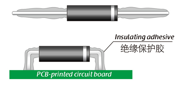
Common treatment methods for surface adhesive insulation:

Characteristics of insulation adhesive material:

1. Silicone material usually presents a transparent and elastic rubber state after curing, which is more effective in shock resistance and can also withstand severe stress changes caused by large high and low temperature changes (-40 ° C~200 ° C).

2. Acrylic materials typically exhibit a transparent and hard coating after curing, with low moisture absorption and fast curing time, as well as excellent wear resistance and insulation.

3. After curing, Urethane material usually presents a transparent and hard coating, which has superior wear resistance and good moisture resistance. Its performance is particularly stable in low temperature environments, but it is less resistant to high temperatures.

4. The coating material based on epoxy is very sturdy and usually opaque, with good moisture and moisture resistance. Its resistance to chemical corrosion and wear is also very good. In addition, epoxy also has good dielectric properties.

Here, suitable insulation adhesive materials can be selected based on the different usage situations of engineers.

HVDIODE - Suly Electronics Co., Ltd.

Expects To Provide You With Perfect Service

Name
Email *
Verification Code *
Click to verify
Leave a message
Name
Email *
Message
Verification Code *
Click to verify
We use Cookie to improve your online experience. By continuing browsing this website, we assume you agree our use of Cookie.