• 2CL70 Fast Recovery High Voltage Diode 6KV 5mA 80nS
  • 2CL70 Fast Recovery High Voltage Diode 6KV 5mA 80nS
  • 2CL70 Fast Recovery High Voltage Diode 6KV 5mA 80nS
  • 2CL70 Fast Recovery High Voltage Diode 6KV 5mA 80nS
  • 2CL70 Fast Recovery High Voltage Diode 6KV 5mA 80nS
  • 2CL70 Fast Recovery High Voltage Diode 6KV 5mA 80nS

2CL70 Fast Recovery High Voltage Diode 6KV 5mA 80nS

Products Main features:
1、Axial leaded connection.
2、High thermal conductivity epoxy compound molding.
3、Low internal resistance reduces energy loss.
4、Special passivation glue chip protection
5、Excellent discharge characteristics.
  • 2CL70 Fast Recovery High Voltage Diode 6KV 5mA 80nS
  • 2CL70 Fast Recovery High Voltage Diode 6KV 5mA 80nS
  • 2CL70 Fast Recovery High Voltage Diode 6KV 5mA 80nS
  • Desciption

  • data sheet

  • Installation Guide

Product Overview

Axial-leaded and molded in epoxy, this is the 6 kV step of the 2CL7 fast-recovery high voltage diode family: a through-hole rectifier for the high-voltage side of X-ray generator tanks, multiplier ladders and DC supplies. It is the part a designer reaches for when the reverse voltage across the diode has to be held off reliably inside a sealed, oil-filled or potted assembly where nothing can be serviced afterwards.

Its job in the circuit is easy to state and harder to get right. In the forward direction it should conduct with a small, predictable loss. When the voltage flips it has to stop conducting quickly, so reverse current does not linger and heat the junction through the switch-off edge. That recovery figure is what separates this family from an ordinary mains rectifier and what makes the part usable in the switching stages of an imaging supply.

Engineers specify the 6 kV class when the peak reverse voltage on the diode sits comfortably below that figure, including the transient overshoot a multiplier or a tank circuit throws at it. The whole family shares one body style and one lead form, so a board laid out around the 4 kV or 8 kV step can be re-populated with this one when the voltage budget changes, without touching the layout.

In service the part is soldered to a board and then immersed, potted or left in air. What surrounds it matters as much as the rating does, so the sections below treat the medium, the mounting and the coating as part of the specification rather than as an afterthought.

Key Features

  • Axial leaded connection — straight solderable leads let the diode mount on a conventional through-hole board, in a hand-wired multiplier ladder, or across a terminal post inside a tank. There is no socket or carrier to source, and every joint can be inspected visually after soldering.
  • High thermal conductivity epoxy molding — the body is a molded epoxy compound rather than a shell over a loose chip. Heat leaves the junction through the molding, and the same molding seals the chip against oil, potting compound and humidity, which is what keeps the electrical behaviour steady once the part is closed inside an assembly.
  • Low internal resistance for lower forward loss — at the current this part is rated for, forward conduction is a small share of the thermal budget, and a low-resistance path keeps it that way. That matters most in a potted module where there is no air movement to carry heat away from the body.
  • Special passivation glue chip protection — the chip surface is treated before encapsulation, because that surface is where the electric field concentrates at kilovolt levels. Protecting it is what allows the part to sit at its rated blocking voltage without surface effects creeping in over time.
  • Good discharge behaviour — capacitor-discharge and multiplier circuits hit the diode with short, sharp current pulses rather than a smooth sine wave. The surge rating covers that short-pulse case, so the part survives a switching transient that the steady-state current figure says nothing about.
  • Ratings published with their test conditions — every figure in the table below carries the condition it was measured under, so a design review can check real margin instead of taking a headline number on trust.

Voltage Class Comparison

  • Within the 2CL7 family this part sits between the 4 kV and 8 kV steps, and all three share the same body style, current class and recovery speed. The choice between them is therefore a question of reverse voltage and forward drop, not of speed or footprint.
  • The blocking figure is a capability, not a target. Design to the peak reverse voltage the diode actually sees — supply output plus the overshoot from switching, ringing and any flashover event — and keep margin above it. If that peak lands at four to five kilovolts, this part gives a sane margin without dragging the rest of the string into a higher forward-drop class.
  • That is the practical reason not to reach for the top of the range by default. Forward peak voltage rises with blocking voltage in this family: the 8 kV part carries a higher forward peak figure than this one, and the 4 kV part sits lower still. In a potted stack with no forced air, a higher forward drop converts directly into junction temperature, and thermal margin is usually harder to buy back than voltage margin.
  • Step up to the 8 kV part when the reverse voltage genuinely approaches 6 kV, when the tank can produce unclamped transients you cannot quantify, or when your own design rules require a fixed derating percentage on blocking voltage. Step down to the 4 kV part when each diode in a multiplier ladder only ever sees one stage's worth of voltage.
  • Before committing, work out the peak reverse voltage with ringing included, look at what happens to reverse current at your real operating temperature rather than at room temperature, and confirm the available thermal path can absorb the forward loss at your duty cycle. Those three checks decide more designs than the headline kilovolt number does.
  • Start from the string voltage, not from a part count. Two 6 kV devices in series give 12 kV on paper and three give 18 kV, but the figure that has to be designed to is the peak reverse voltage the whole string sees, including switching overshoot and any flashover transient. Set that number first, then give each device real margin below its own 6 kV rating instead of running every diode at its ceiling.
  • Reverse voltage does not divide evenly by itself. In a series string of high voltage diodes the standing voltage follows reverse leakage: the device that leaks least ends up holding the most, so three identical-looking parts can carry noticeably different shares. Assume some imbalance and derate the string for it; a string planned as 2 × 6 kV should not be asked to hold a full 12 kV continuously.
  • Allow for the leakage shift with temperature. On this diode the reverse peak current is 2.0 μA maximum at 25 °C and 20.0 μA maximum at 100 °C, a tenfold rise. A string balanced on the bench can drift as the tank or enclosure warms, so check the division at the temperature the assembly actually reaches in service, not only at room temperature.
  • Keep one string to one voltage class and, where possible, one production lot. Mixing a 4 kV step with an 8 kV step in the same string is not forbidden, but their leakage and capacitance differ, so the division changes and the design has to account for it. Parts from a single lot also start out closer to each other than parts drawn from several batches.
  • Fast edges divide by capacitance rather than by leakage. With an 80 nS recovery time, the instant the string turns off the voltage splits according to device and stray capacitance, so lay the string out symmetrically, keep lead lengths equal and avoid long loops or a lead routed close to a neighbouring body. A tidy, symmetric string is easier to grade and easier to diagnose.
  • Equalising resistors are the usual way to force the division. A resistor across each diode makes the voltage follow resistance instead of leakage, but the resistor has to be rated for the DC voltage it stands off and low enough to swamp the leakage it is balancing. Send us the string voltage and device count and we will check the values against this part before you commit to a board.
  • Treat the whole string as one insulation system. In oil or gas the field runs along the chain of bodies and leads, so space the diodes apart, keep bends away from the epoxy seal, clean flux residue off every joint and keep the medium dry. A string that is fine cold can track once the assembly warms and the surfaces are no longer clean.
  • Test the assembled string before it is potted or the tank is closed. Measure reverse current at assembly level with the full string voltage applied, per stage where the joints are still reachable, and record the figures. A weak or misoriented device found at this point is a rework; the same fault found after encapsulation is a scrapped assembly.

Typical Applications

  • X-ray generator tanks — the rectifier stack inside an oil-filled tank is the classic home for this part. Each diode in the stack holds off its share of the tank voltage, and the oil handles both the external insulation and the cooling.
  • DR and CT high-voltage supplies — imaging supplies need a rectifier that stops conducting fast enough for the switching stage and stays stable as the tank warms. In these builds the 6 kV class is often the working voltage of one multiplier stage rather than of the whole stack.
  • Portable and dental X-ray heads — compact heads split the voltage into more, lower-voltage stages, which is exactly where a tighter voltage class does the same job as a bigger one without the extra forward loss.
  • Industrial NDT X-ray generators — inspection systems run long shifts, so continuous forward loss and the thermal path matter more than they do in a pulsed application.
  • DC high-voltage generators and accelerator or radar supplies — multiplier and rectifier strings in these supplies are built from parts chosen per stage, and the middle of the voltage range is where most of those stages sit.
  • Repair and second-source work — where an obsolete axial diode has to be replaced, the through-hole footprint and the banded cathode make a like-for-like swap practical without a layout change. Across all of these builds the pattern is the same: high voltage diodes sit in strings and each one is chosen for the share of the total it must hold off.

Specifications

ParameterSymbolTest conditionsValue
Repetitive peak reverse voltageVrrmTa = 25 °C, Ir = 2.0 μA6 kV
Peak working reverse voltageVrwmTa = 25 °C, Ir = 2.0 μA6 kV
Average forward currentIf(AV)50 Hz half-sine wave, resistive load, Tbreak = 50 °C5 mA
Reverse recovery timeTrr—80 nS
Surge forward currentIfsm0.01 s, 50 Hz half-sine wave0.5 A
Operating ambient temperatureTa—-55 to +150 °C
Storage temperatureTstg—-55 to +125 °C
Forward peak voltageVfm—≥18.0 V
Reverse peak currentIrrm1VRM = VRRM, Ta = 25 °C2.0 μA
Reverse peak currentIrrm2VRM = VRRM, Ta = 100 °C20.0 μA

Operating Environment

  • Insulating oil — immersion is the recommended service condition for this part. Oil does two jobs at once: it holds off the external field around the body and leads, and it carries heat away from the molding. Keep the bath clean and dry, because moisture and particles undo both jobs at the same time.
  • Insulating gas — also a recommended medium. Gas clears the discharge path around the body provided the enclosure is sealed and holds its design pressure, since dielectric strength in gas depends on pressure and purity. Check the assembly at working pressure, not only at fill.
  • Secondary packaging or potting — a potted module protects the diode mechanically and electrically, but the encapsulant also becomes part of the thermal path. A compound with poor heat transfer pushes junction temperature up even though no electrical rating has changed, so choose the potting material for heat flow as carefully as for insulation.
  • Exposed air or forced air cooling — the hardest environment for a body this compact. In air the discharge path runs across the molded surface and along the leads, and heat leaves only by convection. Where the diode must run exposed, fit insulated electrodes at both ends, keep the surface clean, and add airflow if the forward dissipation is continuous rather than pulsed.
  • Clearance and creepage — in every medium, the distance along the body and the leads is part of the insulation system. Flux residue, dust, or a bend formed tight against the body shortens that distance, and a path that looks fine cold can track once the assembly warms up.
  • Fix the medium early — oil, gas, potting and air each call for different installation detail, and the decision is far easier to make at drawing stage than after the tank is filled.

Insulating Adhesive Materials

MaterialCured appearanceKey propertiesTypical use
SiliconeTransparent, elastic rubberAbsorbs shock and tolerates severe stress from -40 °C to 200 °C swingsPotted modules in equipment that cycles hot and cold
AcrylicTransparent, hard filmLow moisture absorption, fast cure, good wear resistance and insulationBoards that need a hard, quick-curing coat
UrethaneTransparent, hard filmGood wear and moisture resistance, stable when cold, less tolerant of high heatCold-running assemblies exposed to mechanical wear
EpoxyUsually opaque, very hardStrong moisture and chemical resistance, good wear and dielectric propertiesRigid encapsulation where opacity is acceptable

Installation Guide

  1. Read the polarity before forming anything. The cathode end is marked with a band on the molded body; match that band to the silkscreen or the wiring diagram and keep the mark visible after assembly wherever the layout allows.
  2. Form and trim the leads with the bend supported away from the body. Bending a lead flush against the epoxy seal stresses the lead-to-chip joint, and that kind of damage usually shows up months later rather than at first power-up.
  3. Mount the body clear of the board and of neighbouring components. On a high-voltage assembly the molded surface is part of the insulation, so anything touching or crowding it changes the field around the part.
  4. Solder at the lead, not at the body. Keep the heat on the joint, and let the lead cool between operations when two joints are made close together — the molding is the seal, and it does not need to see soldering temperature.
  5. Clean flux residue from the body and the leads before the assembly moves on. On a kilovolt part, a residue film is a leakage path waiting for a humid day.
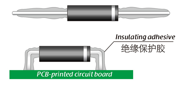
  6. If the assembly will run in air, apply the insulating adhesive or coating chosen for the environment, cure it fully, and only then apply voltage. A partly cured coating insulates far less than a fully cured one.
  7. Check the assembly rather than the part alone: measure reverse current and run an insulation check at assembly level before the tank is closed or the module is potted. A fault found here is rework; the same fault found afterwards is a scrapped assembly.

Ordering & Delivery

Orders run from a handful of parts for a prototype or a repair to scheduled production pulls. As high voltage diode manufacturers we quote the same parameter set either way. Tell us the working voltage, the medium the diode will sit in, the quantity and the date you need it, and the reply comes back with a part recommendation rather than a price list alone. When the requirement sits close to the edge of this voltage class, say so — moving you to the 4 kV or 8 kV step before the order is far easier than correcting it afterwards.

Every model is supplied with its data sheet, package drawing and installation guide. Packing format depends on the quantity and on how the parts will be fed onto the board, so confirm whether you need bulk or a taped format when you order. Shipments go by international express, which suits prototype and repair lots as well as scheduled production pulls; confirm the delivery terms, the paperwork your country requires and the current lead time with your sales contact at the time of ordering.

After delivery the same team answers mounting, potting and start-up questions. If a diode behaves unexpectedly in an assembly, send the operating conditions and the measured figures — most issues trace back to the medium, the clearance or the way the part is mounted rather than to the component itself, and that is usually settled in one exchange.

Technical Support & Model Matching

Selection starts with your circuit, not a catalogue number: tell us the working voltage, load current, switching frequency and ambient cooling conditions, and our engineers will match a model from our range and explain the margin left in the design. Each model ships with its datasheet, package drawing and installation guide, and we stay available for mounting and soldering questions, start-up checks and fault finding when an existing part runs hot or fails early. Orders run from about 7 days to 6 months depending on quantity, usually by international express.
FAQ

Which end of the body marks the cathode?

The cathode end carries a band on the molded body; the banded end is the cathode and the plain end is the anode. Match the band to the cathode mark on your board or wiring diagram. If the marking has been cleaned off an old part, identify the orientation from the circuit rather than guessing, because a reverse-connected diode in a high-voltage string will not survive first power-up.

What is the difference between Vrrm and Vrwm?

Vrrm is the repetitive peak reverse voltage the part may see cycle after cycle; Vrwm is the working peak used in normal operation. On this high voltage diode both are quoted at the same value, measured at 25 °C with a stated reverse current, so there is no separate working derating to remember. Treat that figure as your ceiling including repetitive transients, not as an average operating level.

Can several of these be stacked in series to block more voltage?

In principle yes — series strings are how high-voltage rectifier stacks reach voltages above a single part's rating, and this family is built in voltage steps for exactly that reason. What needs care is sharing: differences in reverse leakage between devices, plus stray capacitance, decide how the total divides, and an unbalanced string can put more stress on one diode than on its neighbours. Keep parts from the same production lot together in a string, allow extra margin per device, and ask us to review the string layout before you build it.

How do I check whether this part matches the diode I am replacing?

Start with the marking on the old body and compare it against the figures on this product: reverse voltage class, average forward current, recovery time, forward peak voltage, then the lead form and body shape. If the old number is unreadable or obsolete, send a photo of the part in its board position together with the supply's voltage and current. As high voltage diode manufacturers we hold the parameter set for the whole family and can tell you which voltage step lines up and which ones do not.

Do I need a fast-recovery part for 50/60 Hz rectification?

Usually not. At mains frequency the reverse voltage stays negative for milliseconds, so recovery speed barely enters the thermal or timing budget, and a power-frequency diode is the simpler choice. The 80 nS recovery of this part earns its place in switching supplies, in multiplier stages driven by a pulsed source, and in capacitor-discharge circuits — anywhere the diode is asked to stop conducting quickly. Fast-recovery high voltage diodes are specified for those jobs, not because a lower recovery number is automatically better.

The selection of high-voltage diodes is closely related to their usage environment。

1. Used in insulating oil. (Recommended)
2. Used in insulating gases. (Recommended)
3. Secondary packaging use. (High requirements for heat dissipation and other parameter performance of components)
4. Use in exposed air or add air cooling. (If the size of the high-voltage diode is small, it is easy to discharge, and the heat dissipation performance is average.)

For high-voltage diodes used in exposed air, it is recommended to install them with insulated electrodes at both ends.


Common treatment methods for surface adhesive insulation:

Characteristics of insulation adhesive material:

1. Silicone material usually presents a transparent and elastic rubber state after curing, which is more effective in shock resistance and can also withstand severe stress changes caused by large high and low temperature changes (-40 ° C~200 ° C).

2. Acrylic materials typically exhibit a transparent and hard coating after curing, with low moisture absorption and fast curing time, as well as excellent wear resistance and insulation.

3. After curing, Urethane material usually presents a transparent and hard coating, which has superior wear resistance and good moisture resistance. Its performance is particularly stable in low temperature environments, but it is less resistant to high temperatures.

4. The coating material based on epoxy is very sturdy and usually opaque, with good moisture and moisture resistance. Its resistance to chemical corrosion and wear is also very good. In addition, epoxy also has good dielectric properties.

Here, suitable insulation adhesive materials can be selected based on the different usage situations of engineers.

HVDIODE - Suly Electronics Co., Ltd.

Expects To Provide You With Perfect Service

Name
Email *
Verification Code *
Click to verify
Leave a message
Name
Email *
Message
Verification Code *
Click to verify
We use Cookie to improve your online experience. By continuing browsing this website, we assume you agree our use of Cookie.