Eight kilovolts is the top of the 2CL7 axial family, and the 2CL71 is the step that lets a rectifier string hold its margin without adding another body to the stack. Average forward current is 5 mA, reverse recovery is 80 nS, and the package is a molded epoxy cylinder with straight leads and a banded cathode — a through-hole part of the kind high voltage diode manufacturers build for the secondary side of an imaging or industrial supply, where the voltage is high, the current is small and nothing can be serviced once the tank is closed.
In circuit it has two jobs. Forward, it should conduct with a small and predictable loss. At the switch-off edge it has to stop conducting quickly, because reverse current that lingers becomes heat at the junction; the 80 nS recovery figure is what separates this family from an ordinary mains rectifier and what makes it usable in the switching stages of an X-ray generator supply.
Every rating is published with the condition behind it: blocking voltage at 2.0 µA of reverse leakage, average current into a 50 Hz half-sine wave with a resistive load at Tbreak = 50 °C, and reverse leakage at 25 °C and again at 100 °C. That turns a design review into arithmetic and shows how the part behaves hot before anything is frozen on a drawing.
The 2CL69 at 4 kV, the 2CL70 at 6 kV and the 2CL71 at 8 kV share one body, one lead form, one 5 mA current class and one 80 nS recovery time. What changes is blocking voltage and forward peak voltage: ≥16.0 V, ≥18.0 V and ≥23.0 V respectively. The choice between them is therefore a question of headroom against conduction loss, not of speed or footprint.
Headroom is what the extra kilovolts buy. A multiplier string, a tank that sees mains regulation swings, or a chain of devices in series all accumulate tolerances, and the larger class keeps the string clear of its leakage knee under worst-case conditions rather than nominal ones. It also shortens the string: fewer bodies, fewer joints, less accumulated forward drop and a shorter assembly where the tank has no room to spare.
The cost is forward drop. In a potted stack with no airflow, every extra volt of forward peak voltage becomes junction temperature, so if the peak reverse voltage on the device — including the overshoot a multiplier or a tank circuit throws at it — sits comfortably below 6 kV, the 6 kV step runs cooler at the same current and speed, and the 4 kV step runs cooler again for the lower-voltage stages of a long string.
Blocking voltage is specified at 2.0 µA of leakage, which makes it a working rating rather than a destruction limit: it is the voltage the part holds while leaking that much. Leakage is also ten times higher at 100 °C than at 25 °C, so a string balanced on the bench drifts as the tank warms, and equalising resistors or leakage-sensitive sensing have to be sized on the hot figure. Because all three steps are published against the same test conditions, the comparison can be finished on paper — the kind of documentation high voltage diode manufacturers should give a designer before a stack is committed.
Most of these parts end up inside a sealed high-voltage assembly. In medical imaging the 2CL71 sits in the rectifier stack of an X-ray generator tank, in the high-voltage section of a DR or CT supply, and in the compact head of a portable dental panoramic unit, where the voltage is split into fewer, larger stages to save space and an 8 kV body keeps both the part count and the joint count down. Industrial inspection brings the same requirement to non-destructive testing generators, which run long shifts and care about continuous forward loss and a steady thermal path more than about peak capability.
Outside imaging, the part appears in DC high-voltage generators and in accelerator or radar supplies, in multiplier and rectifier stages built from high voltage diodes where the higher-voltage stages are the ones that need the 8 kV class. Repair work is the other steady user: the through-hole footprint, the banded cathode and the published leakage figures make a like-for-like swap practical on a board that will not be relaid, and the 8 kV rating covers equipment originally built around a higher-voltage part.
| Parameter | Symbol | Test conditions | Rating |
|---|---|---|---|
| Repetitive peak reverse voltage | Vrrm | Ta = 25 °C, Ir = 2.0 µA | 8 kV |
| Peak working reverse voltage | Vrwm | Ta = 25 °C, Ir = 2.0 µA | 8 kV |
| Average forward current | If(AV) | 50 Hz half-sine wave, resistive load, Tbreak = 50 °C | 5 mA |
| Reverse recovery time | Trr | — | 80 nS |
| Surge forward current | Ifsm | 0.01 s, 50 Hz half-sine wave | 0.5 A |
| Forward peak voltage | Vfm | — | ≥23.0 V |
| Reverse peak current | Irrm1 | VRM = VRRM, Ta = 25 °C | 2.0 µA |
| Reverse peak current | Irrm2 | VRM = VRRM, Ta = 100 °C | 20.0 µA |
| Operating ambient temperature | Ta | — | -55 to +150 °C |
| Storage temperature | Tstg | — | -55 to +125 °C |
| Construction | — | — | Axial leaded, epoxy molded, passivated chip with insulating glue protection |
| Position in the range | — | — | 8 kV step of the 2CL7 series (4 kV, 6 kV, 8 kV) |
Selection starts with your circuit, not a catalogue number: tell us the working voltage, load current, switching frequency and ambient cooling conditions, and our engineers will match a model from our range and explain the margin left in the design. Each model ships with its datasheet, package drawing and installation guide, and we stay available for mounting and soldering questions, start-up checks and fault finding when an existing part runs hot or fails early. Orders run from about 7 days to 6 months depending on quantity, usually by international express.
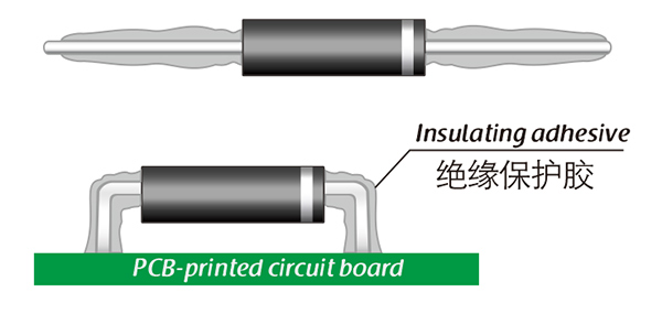
Here, suitable insulation adhesive materials can be selected based on the different usage situations of engineers.