| Parameter | Value |
|---|---|
| Repetitive peak reverse voltage (Vrrm) | 18 kV at Ta = 25 °C, Ir = 2.0 µA |
| Peak working reverse voltage (Vrwm) | 18 kV at Ta = 25 °C, Ir = 2.0 µA |
| Average forward current (If(AV)) | 5 mA, 50 Hz half-sine wave, resistive load, Tbreak = 50 °C |
| Reverse recovery time (Trr) | 80 nS |
| Surge forward current (Ifsm) | 0.5 A, 0.01 s half-sine wave at 50 Hz |
| Forward peak voltage (Vfm) | ≥ 43.0 V |
| Reverse leakage at 25 °C (Irrm1) | 2.0 µA at VRM = VRRM |
| Reverse leakage at 100 °C (Irrm2) | 20.0 µA at VRM = VRRM |
| Operating ambient temperature (Ta) | -55 °C to +150 °C |
| Storage temperature (Tstg) | -55 °C to +125 °C |
| Package | Axial leaded, epoxy molded, cathode band marked |
| Leads | Formable for board or stack mounting, insulating adhesive at the bend |
| Environment | Status | What it means for the assembly |
| Insulating oil | Recommended | Raises the dielectric strength around the body and helps carry heat away from it |
| Insulating gas | Recommended | Gives long creepage paths around the body where oil is impractical |
| Secondary packaging or potting | Check the thermal path | Heat has to leave through the compound around the diode, so the enclosure becomes part of the thermal design |
| Exposed air | Use with care | The small body discharges more easily and dissipates heat less effectively than in oil or gas |
| Exposed air with insulated electrodes at both ends | Recommended practice | Insulates the terminations where the part has to run in free air |
| Added air cooling | Partial measure | Lowers body temperature but leaves the clearance and insulation requirements exactly as they were |
The adhesive around the lead bend decides how well that termination behaves at high voltage, and the four common chemistries that high voltage diode manufacturers work with behave differently. Silicone usually ends up as a transparent, elastic rubber after curing: it absorbs shock and rides out the severe stress of rapid temperature swings from -40 °C to 200 °C, which suits assemblies that cycle hard or see vibration. Acrylic cures to a transparent, hard coating with low moisture absorption, a fast cure time and excellent wear resistance and insulation — a practical match for a line that needs the part coated and moving on quickly. Urethane also cures hard and clear, with superior wear resistance and good moisture resistance; its performance is particularly stable in low temperature environments, but it is less resistant to high temperatures, so it suits cold-running assemblies rather than hot ones. Epoxy-based coatings are very sturdy and usually opaque, with good moisture resistance, very good resistance to chemical corrosion and wear, and good dielectric properties — the choice for rigid potted modules where the coating has to survive the environment rather than flex with it.
Pick by the situation the high voltage diode will actually see. Oil-filled and gas-filled assemblies generally tolerate a harder coating, while parts that will be handled, vibrated or thermally cycled benefit from the elastic behaviour of silicone. Whatever the choice, clean the surface first: an adhesive applied over flux residue seals the contamination in, and the leakage problem simply moves under the coating.
Selection starts with your circuit, not a catalogue number: tell us the working voltage, load current, switching frequency and ambient cooling conditions, and our engineers will match a model from our range and explain the margin left in the design. Each model ships with its datasheet, package drawing and installation guide, and we stay available for mounting and soldering questions, start-up checks and fault finding when an existing part runs hot or fails early. Orders run from about 7 days to 6 months depending on quantity, usually by international express.
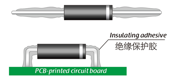
Here, suitable insulation adhesive materials can be selected based on the different usage situations of engineers.