• 2CL77 Fast Recovery High Voltage Diode 20KV 5mA 80nS
  • 2CL77 Fast Recovery High Voltage Diode 20KV 5mA 80nS
  • 2CL77 Fast Recovery High Voltage Diode 20KV 5mA 80nS
  • 2CL77 Fast Recovery High Voltage Diode 20KV 5mA 80nS
  • 2CL77 Fast Recovery High Voltage Diode 20KV 5mA 80nS
  • 2CL77 Fast Recovery High Voltage Diode 20KV 5mA 80nS

2CL77 Fast Recovery High Voltage Diode 20KV 5mA 80nS

Products Main features:
1、Axial leaded connection.
2、High thermal conductivity epoxy compound molding.
3、Low internal resistance reduces energy loss.
4、Special passivation glue chip protection
5、Excellent discharge characteristics.
  • 2CL77 Fast Recovery High Voltage Diode 20KV 5mA 80nS
  • 2CL77 Fast Recovery High Voltage Diode 20KV 5mA 80nS
  • 2CL77 Fast Recovery High Voltage Diode 20KV 5mA 80nS
  • Desciption

  • data sheet

  • Installation Guide

A 20KV Axial Rectifier for Multiplier Stages

The 2CL77 is a fast recovery high voltage diode rated 20KV, and it holds the middle of the 2CL7 axial range. Its 5mA average forward current, 80nS recovery time and 0.5A surge rating are shared with the 16KV, 18KV and 30KV parts, so the four models differ in blocking voltage and in little else. Between 18KV and 20KV even the forward peak stays at ≥43.0V, which makes the extra two kilovolts a margin that costs nothing in conduction loss. Both blocking figures, repetitive peak and working peak, are quoted at 20KV with 2.0µA of reverse current flowing at 25 °C. Tying a rating to a leakage condition is what makes it usable in a design: the part is expected to hold the full 20KV in service, not only for an instant. The body is a moulded epoxy cylinder with two axial leads and a band at the cathode. It solders into a board, wires point to point into a multiplier ladder, or sits in an oil-filled or potted shell, and the leads form to the hole pitch without special tooling. Every step of the ladder is published by HVDIODE, Suly Electronics Co., Ltd., with its own rating table, test conditions and dimension drawing, in one table format from 16KV to 30KV — the property that lets the figures line up when high voltage diode manufacturers are put side by side. Step | Blocking voltage (Vrrm = Vrwm) | Forward peak voltage | What changes against the step below --- | --- | --- | --- 2CL75 | 16KV | ≥41.0V | Smallest blocking class in the family 2CL76 | 18KV | ≥43.0V | 2KV more blocking, 2V more forward drop 2CL77 | 20KV | ≥43.0V | 2KV more blocking, no change in forward drop 2CL82 | 30KV | ≥52.0V | 10KV more blocking, 9V more forward drop

Construction Details That Matter at 20KV

  • Axial leads on a moulded epoxy body — The two leads suit a PCB joint, a point-to-point run in a multiplier ladder or a fixed position inside a potted shell, and they form to the hole pitch without extra hardware. - High thermal conductivity epoxy — The compound carries heat from the chip stack into the body and the leads, and seals the junction from humidity and surface contamination, which is what keeps the reverse characteristic steady as an assembly warms up. - Low internal resistance — Conduction loss stays small at 5mA, and the forward drop holds from one part to the next in a string, so the total drop along a multiplier can be added up from the datasheet figure. - Passivation over the chip surface — The passivation layer holds surface leakage down at 20KV, and surface leakage is the failure mode most high voltage diodes reach first in a warm, contaminated enclosure.

Where the 20KV Step Is Used

Imaging power supplies are the usual home for this voltage class. X-ray, DR, CT and dental panoramic generators rectify at high potential inside multiplier stages, and 20KV covers the intermediate stages of those stacks. Industrial high-voltage test and inspection equipment — NDT sets, DC high-voltage generators, HV test transformers — runs at currents the 5mA rating covers, and accelerator and radar supplies use series strings where a defined reverse margin at modest current counts for more than forward capability. Repair and maintenance is the other steady use. Where a stack has failed, the number on the old part is the place to start; the rest of the ladder shares the current, recovery and surge behaviour, so high voltage diodes one step either side of the original are a workable substitution once the reverse margin in the stack has been checked. Prototype and pre-production builds suit the axial format as well, because the leads are hand-solderable and a first article can be assembled without a reflow profile.

Working Inside the 5mA Forward Rating

The 5mA figure is an average forward current at 50Hz half-sine into a resistive load with Tbreak at 50 °C, and it is the continuous ceiling for this package. It fits the high-voltage side of a supply, where each diode in a multiplier carries only the stage current, but it does not fit a main power path: a design that needs hundreds of milliamps at a few kilovolts belongs in the SMD 5KV range, where a single footprint covers 100mA to 900mA at 75nS.

The other edge is voltage. The ladder stops at 30KV, so a stack that needs more reverse blocking gets more diodes in series rather than a different model, and the forward drops then add along the string.

2CL77 Ratings and Test Conditions

Parameter (symbol)Rating and test condition
Repetitive peak reverse voltage (Vrrm)20KV at Ta = 25 °C, Ir = 2.0µA
Peak working reverse voltage (Vrwm)20KV at Ta = 25 °C, Ir = 2.0µA
Average forward current (If(AV))5mA, 50Hz half-sine, resistive load, Tbreak = 50 °C
Recovery time (Trr)80nS
Surge forward current (Ifsm)0.5A, 0.01s half-sine, 50Hz
Forward peak voltage (Vfm)≥43.0V
Reverse leakage at 25 °C (Irrm1)2.0µA at VRM = VRRM
Reverse leakage at 100 °C (Irrm2)20.0µA at VRM = VRRM
Operating ambient temperature (Ta)-55 to +150 °C
Storage temperature (Tstg)-55 to +125 °C

Fitting the Diode Into a High-Voltage Assembly

  1. Form the leads before soldering: support the lead at the body, keep the bend clear of the epoxy seal, and set a stand-off so the body does not rest against the board surface.
  2. Keep the cathode band facing the same way through the whole string, so a replacement goes in exactly as the part it replaces.
  3. Solder with the lead supported and the heat brief; the body should carry no mechanical load from the joint.
  4. Clean flux residue from the body and the leads afterwards. At 20KV the surface path between the leads is part of the insulation, and flux, dust or fingerprints shorten it.
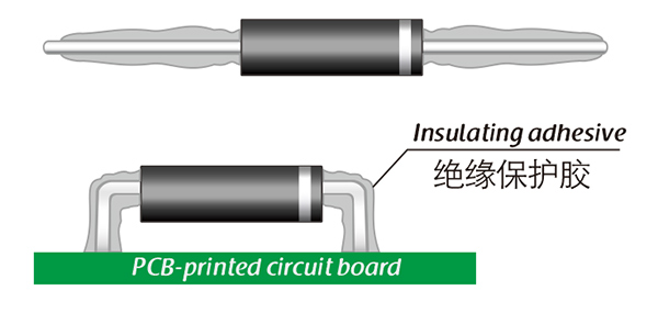
  5. Dress the lead junction with insulating adhesive once the joint has been inspected — sharp points are where corona starts, and this is the practice high voltage diode manufacturers recommend for oil-filled and potted stacks.
  6. Choose the medium deliberately: insulating oil is the recommended environment, insulating gas is next, and open air needs insulated electrodes at both ends plus forced cooling.
  7. In a potted shell, plan the thermal path: the surrounding compound becomes part of the insulation and carries the heat, so the electrical margins have to hold at the internal temperature.
  8. Test the finished stack at working voltage before it is sealed, and again at working temperature if the design watches leakage.

Potting and Coating Materials

MaterialCured stateWhere it suits
SiliconeTransparent, elastic rubberStacks that see shock and wide temperature swings, roughly -40 °C to +200 °C
AcrylicTransparent, hard coatingFast-curing coverage where moisture absorption stays low and the coating resists wear
UrethaneTransparent, hard coatingLow-temperature assemblies needing wear and moisture resistance, least tolerant of sustained heat
EpoxyOpaque, very rigidChemical, moisture and wear exposure where dielectric strength matters most, and the hardest to rework

From Order to Dispatch

The same build is available at 16KV, 18KV and 30KV, so a change of margin mid-project does not change the package or the datasheet layout. The rating table and the dimension drawing go with the order. Delivery is by International express.

Technical Support & Model Matching

Selection starts with your circuit, not a catalogue number: tell us the working voltage, load current, switching frequency and ambient cooling conditions, and our engineers will match a model from our range and explain the margin left in the design. Each model ships with its datasheet, package drawing and installation guide, and we stay available for mounting and soldering questions, start-up checks and fault finding when an existing part runs hot or fails early. Orders run from about 7 days to 6 months depending on quantity, usually by international express.
FAQ

What does the 20KV rating on this high voltage diode cover?

Both blocking figures. Repetitive peak reverse voltage and peak working reverse voltage are each quoted at 20KV, measured with 2.0µA of reverse current flowing at 25 °C, so the full 20KV is available as working voltage rather than as a one-off peak. The only surge figure published for this part is forward — 0.5A for a 0.01s half-sine — so treat 20KV as the ceiling for every reverse excursion the stack can produce, including start-up transients and commutation spikes.

How does the 2CL77 compare with the 18KV and 30KV steps?

All four steps in the ladder share 5mA, 80nS and a 0.5A surge rating. 2CL76 at 18KV and 2CL77 at 20KV also share the same ≥43.0V forward peak, so the extra two kilovolts add blocking margin without adding conduction loss. 2CL82 at 30KV raises the forward peak to ≥52.0V, and that 9V difference has to be budgeted at every diode in the string — which is the reason to take 30KV only when the stack genuinely sits near it.

What does a ≥43.0V forward peak mean for a multiplier string?

At the 5mA average rating a single diode dissipates roughly 0.2W, which is small on its own. In a multiplier the drops add along the string, so the whole chain appears as output loss and as heat inside a potted or oil-filled assembly; add up every position in the string rather than looking at one part when the thermal path is worked out.

What does the 0.5A surge rating cover?

It is a 0.01s half-sine at 50Hz. It covers the charging current when a capacitor bank first fills and the discharge pulse that follows a flashover inside the stack. The figure is non-repetitive, so pulses that arrive close together accumulate stress even when each one is individually inside the limit.

Is the 2CL77 a direct replacement for a 2CL76 or 2CL82?

Mechanically yes — same axial body, same leads, same 5mA, 80nS and 0.5A behaviour. Electrically the reverse margin changes: stepping up from 2CL76 adds 2KV of blocking at no cost in forward drop, while stepping down from 2CL82 removes 10KV of margin and 9V of forward drop. Check the worst-case peak across each position in the stack before substituting; the other high voltage diodes in the ladder can then be swapped on that basis.

Where does the rating data on this product come from?

From the 2CL77 rating table published by HVDIODE, Suly Electronics Co., Ltd., with a test condition beside every figure: 20KV at 2.0µA and 25 °C, 5mA into a resistive load at 50Hz half-sine, and leakage at both 25 °C and 100 °C. The dimension drawing for the axial body comes from the same source, so the electrical and mechanical data stay in step — worth keeping with the design record, particularly where parts from several high voltage diode manufacturers have been qualified against the same stack.

The selection of high-voltage diodes is closely related to their usage environment。

1. Used in insulating oil. (Recommended)
2. Used in insulating gases. (Recommended)
3. Secondary packaging use. (High requirements for heat dissipation and other parameter performance of components)
4. Use in exposed air or add air cooling. (If the size of the high-voltage diode is small, it is easy to discharge, and the heat dissipation performance is average.)

For high-voltage diodes used in exposed air, it is recommended to install them with insulated electrodes at both ends.


Common treatment methods for surface adhesive insulation:

Characteristics of insulation adhesive material:

1. Silicone material usually presents a transparent and elastic rubber state after curing, which is more effective in shock resistance and can also withstand severe stress changes caused by large high and low temperature changes (-40 ° C~200 ° C).

2. Acrylic materials typically exhibit a transparent and hard coating after curing, with low moisture absorption and fast curing time, as well as excellent wear resistance and insulation.

3. After curing, Urethane material usually presents a transparent and hard coating, which has superior wear resistance and good moisture resistance. Its performance is particularly stable in low temperature environments, but it is less resistant to high temperatures.

4. The coating material based on epoxy is very sturdy and usually opaque, with good moisture and moisture resistance. Its resistance to chemical corrosion and wear is also very good. In addition, epoxy also has good dielectric properties.

Here, suitable insulation adhesive materials can be selected based on the different usage situations of engineers.

HVDIODE - Suly Electronics Co., Ltd.

Expects To Provide You With Perfect Service

Name
Email *
Verification Code *
Click to verify
Leave a message
Name
Email *
Message
Verification Code *
Click to verify
We use Cookie to improve your online experience. By continuing browsing this website, we assume you agree our use of Cookie.