• 2CL82 Fast Recovery High Voltage Diode 30KV 5mA 80nS
  • 2CL82 Fast Recovery High Voltage Diode 30KV 5mA 80nS
  • 2CL82 Fast Recovery High Voltage Diode 30KV 5mA 80nS
  • 2CL82 Fast Recovery High Voltage Diode 30KV 5mA 80nS
  • 2CL82 Fast Recovery High Voltage Diode 30KV 5mA 80nS
  • 2CL82 Fast Recovery High Voltage Diode 30KV 5mA 80nS

2CL82 Fast Recovery High Voltage Diode 30KV 5mA 80nS

Products Main features:
1、Axial leaded connection.
2、High thermal conductivity epoxy compound molding.
3、Low internal resistance reduces energy loss.
4、Special passivation glue chip protection
5、Excellent discharge characteristics.
  • 2CL82 Fast Recovery High Voltage Diode 30KV 5mA 80nS
  • 2CL82 Fast Recovery High Voltage Diode 30KV 5mA 80nS
  • 2CL82 Fast Recovery High Voltage Diode 30KV 5mA 80nS
  • Desciption

  • data sheet

  • Installation Guide

30 kV Blocking in a Single Axial Body

Every multiplier stage reaches a point where reverse voltage, rather than current, decides how many parts the stack needs. 30 kV is the top of the 2CL axial range, and it changes the arithmetic of a cascade. Where a lower step would put an extra high voltage diode into every stage, one 2CL82 can hold a whole stage voltage by itself — fewer joints to insulate, shorter assemblies, and fewer surfaces across which tracking can start. The trade is on the data sheet rather than buried in it. Every figure in the table below carries its test condition, which is what a design review will ask about.

Construction Detail Behind the Voltage Rating

  • Axial leads at both ends. The diode sits through a board, a bracket or a stack plate without a socket, and the lead itself carries the connection — something you can form, sleeve or pot once it is in place.
  • High thermal conductivity epoxy molding. The encapsulant does two jobs: it seals the junction from the surrounding medium and moves heat out of a chip that has almost no surface area of its own.
  • Low internal resistance. In a multiplier the part conducts in short, high-current pulses, and any resistance inside the body turns into heat at exactly the wrong moment.
  • Passivated chip surface, sealed before molding. The blocking junction is protected before the epoxy goes on, which keeps reverse leakage predictable instead of letting it drift with surface charge.
  • Discharge behaviour. Stages that dump a capacitor through the diode rely on it recovering cleanly after the pulse, inside the 0.5 A surge rating.
  • Banded cathode. A band near one end marks polarity, so orientation stays readable after potting and during a service call.
  • Shared construction across the range. The 16 kV, 18 kV and 20 kV high voltage diodes in this series use the same axial leaded body and cathode marking, so mounting practice carries over when a design moves up or down a step.

Current, Forward Drop and Heat Path

Three figures set what this high voltage diode can and cannot do in a circuit. Average forward current is 5 mA, quoted for a 50 Hz half-sine wave into a resistive load with a break temperature of 50 °C — that is the continuous conduction budget, while pulses are covered separately by 0.5 A for 0.01 s. Forward peak voltage is ≥52.0 V, which at 5 mA works out to roughly a quarter of a watt generated inside the body. A quarter of a watt sounds small until you look at the volume it is generated in. There is no heatsink tab on an axial diode: heat leaves through the two leads and into whatever they are soldered or clamped to. Short leads into a metal bracket, a cooled plate or a filled compound run cooler than long leads hanging in still air inside a sealed enclosure. On a continuously running assembly, treat the leads as part of the thermal design rather than as pure electrical connections. Leakage is the other figure to carry into the design. At the rated reverse voltage the published limits are 2.0 µA at 25 °C and 20 µA at 100 °C. The warmer number is the one that matters inside a sealed tank, because reverse current grows with temperature and adds to the load the stage has to supply; measure and specify it at the temperature the equipment actually reaches.

Assembly and Insulation Practice

  1. Choose the insulating medium before the layout. Oil or insulating gas is the recommended environment at this voltage class, because the medium shares the insulation duty with the package and helps carry heat off the leads.
  2. Clean and dry the body, the leads and the surrounding hardware. At 30 kV a fingerprint or a flux smear across the epoxy is a leakage path, and it shows up long before the chip does.
  3. Set clearances for the medium you are using, not for the part alone. Creepage across a surface is a different problem from clearance through oil or gas, and both need room around a body this size.
  4. Form leads a few millimetres away from the epoxy shoulder and support the lead while you bend it; a bend pressed against the body seal puts mechanical stress exactly where the insulation is thinnest.
  5. Solder with a controlled iron and a short dwell, and clamp or heat-shunt the lead between the joint and the body when the process runs hot.
  6. If the diode has to run in air, fit insulated electrodes at both ends and add forced cooling — still air removes very little heat from two thin leads, and a small body discharges easily across a gap.
  7. Pot or encapsulate with a degassed compound, cured to its supplier's schedule, and keep the coating even around both leads so no void forms at the body surface.
  8. Run a partial-discharge or leakage check at working voltage on the finished assembly and record the reading, so later service work has a baseline.

Circuits That Suit a 30 kV Device

  • Multiplier cascades in imaging generators. Cockcroft–Walton and similar ladders inside X-ray, DR, CT and dental panoramic tanks, where a 30 kV device can hold a full stage and keep the ladder short.
  • Rectifier chains in oil-filled tanks. Stages running at tens of kilovolts and a few milliamps — the working territory of axial high voltage diodes, where holding voltage matters far more than passing current.
  • Accelerator and radar supplies. Bias and rectifier chains in electron accelerator and radar power units, built around kilovolt rails and small standing currents.
  • Non-destructive testing and DC high-voltage test sets. Portable X-ray inspection units and HV test transformers that need a predictable blocking part in a small axial package.
  • Pulse discharge networks. Capacitor discharge circuits that depend on clean recovery after each pulse rather than on continuous conduction.
  • Field replacement. Equipment already in service where the original 30 kV axial part has failed; cross-reference the banded end, the lead spacing and the ratings rather than the part number, since numbering schemes differ between high voltage diode manufacturers.

2CL82 Ratings and Test Conditions

ParameterSymbolRating
Repetitive peak reverse voltageVrrm30 kV at Ta = 25 °C, Ir = 2.0 µA
Peak working reverse voltageVrwm30 kV at Ta = 25 °C, Ir = 2.0 µA
Average forward currentIf(AV)5 mA, 50 Hz half-sine, resistive load, Tbreak = 50 °C
Reverse recovery timeTrr80 nS
Surge forward currentIfsm0.5 A, 0.01 s, 50 Hz half-sine
Forward peak voltageVfm≥52.0 V
Reverse leakage at 25 °CIrrm1≤2.0 µA at VRM = VRRM
Reverse leakage at 100 °CIrrm2≤20.0 µA at VRM = VRRM
Operating ambient temperatureTa-55 to +150 °C
Storage temperatureTstg-55 to +125 °C
Body—Cylindrical epoxy molding, passivated chip
Terminations—Two axial leads, cathode band marked

Potting Compounds for Sealed Assemblies

CompoundAfter cureSuitsKeep in mind
SiliconeClear, elastic rubberTanks and assemblies that cycle hot and cold, or see shock and vibrationFlexible rather than structural, so the diode still needs mechanical support
AcrylicClear, hard coatingThin conformal layers and lines that need a fast cureBetter suited as a coating rather than a cavity fill
UrethaneHard, clear, stable at low temperatureCold-running assembliesThe weakest of the four under sustained heat
EpoxyUsually opaque, rigid, good dielectric strengthEncapsulated modules that will be handled, cleaned and shippedThe rigid cure puts thermal expansion stress on the body interface

Ordering Notes and Delivery

Send the insulating medium, the working peak reverse voltage of the stage, the average current it draws and the number of parts per build, and the right voltage step can be confirmed in one reply. Orders leave by international express. The data sheet and the package drawing can travel with the quotation and are worth filing with incoming inspection, because a rating only means something next to its test conditions. If you are weighing this part against offers from other high voltage diode manufacturers, check that reverse leakage is quoted at the same temperature and the same reverse voltage — figures taken on different test bases cannot be compared. Builds that use more than one voltage step from this series should keep each step on its own line item and its own bin, since mixing them is the usual way a wrong part ends up in a stack.

Technical Support & Model Matching

Selection starts with your circuit, not a catalogue number: tell us the working voltage, load current, switching frequency and ambient cooling conditions, and our engineers will match a model from our range and explain the margin left in the design. Each model ships with its datasheet, package drawing and installation guide, and we stay available for mounting and soldering questions, start-up checks and fault finding when an existing part runs hot or fails early. Orders run from about 7 days to 6 months depending on quantity, usually by international express.
FAQ

Is the 30 kV rating a breakdown voltage?

No. It is a rated blocking figure: 30 kV of repetitive peak reverse voltage held at 25 °C with reverse current at 2.0 µA, and peak working reverse voltage is quoted at the same level. That is the normal way high voltage diodes in this class are specified, so design the stage to stay below it with room for regulation and switching transients rather than treating 30 kV as a threshold to approach.

What forward drop should I budget for at 5 mA?

The published forward peak voltage is ≥52.0 V. At 5 mA that is roughly 0.26 W dissipated inside the body — small in absolute terms, but generated in a very small volume. Carry the drop through the output budget of the stack and give the leads a path for the heat, such as a metal bracket, a cooled plate or a filled compound, instead of assuming the diode runs cool because the current is only a few milliamps.

What temperature range does the 2CL82 work over?

Operating ambient is -55 °C to +150 °C and storage is -55 °C to +125 °C, so storage is the narrower window of the two — worth knowing if parts sit in a warm drying cabinet before assembly. Reverse leakage is published at both 25 °C and 100 °C, and the 100 °C figure is the one that describes behaviour inside a sealed, warmed-up enclosure.

How do I identify the cathode once the assembly is potted?

A band near one end of the cylindrical body marks the cathode, and it stays visible under a clear compound. If you pot in an opaque epoxy, mark the orientation on the assembly drawing and check it against the band before the cavity is filled; after cure there is nothing left to see.

Which potting compound suits a 30 kV assembly?

Silicone is the usual choice where the assembly cycles hot and cold, because it stays elastic and absorbs the stress. Acrylic suits thin conformal coatings, urethane suits assemblies that run cold, and epoxy suits rigid encapsulated modules that will be handled and cleaned. Whichever you use, degas it, cure it to schedule and keep the layer even around both leads — voids and de-bonded patches at the body surface become partial-discharge sites.

What should I check when replacing a failed 30 kV diode in the field?

Three things: the banded cathode end, the lead spacing so the new part drops into the existing terminations, and the ratings — 30 kV blocking, 5 mA average forward current and 80 nS recovery. Check the working voltage of the stack as well, because the replacement has to suit the circuit and not just the part number it replaces, whichever of the high voltage diode manufacturers supplied the original.

The selection of high-voltage diodes is closely related to their usage environment。

1. Used in insulating oil. (Recommended)
2. Used in insulating gases. (Recommended)
3. Secondary packaging use. (High requirements for heat dissipation and other parameter performance of components)
4. Use in exposed air or add air cooling. (If the size of the high-voltage diode is small, it is easy to discharge, and the heat dissipation performance is average.)

For high-voltage diodes used in exposed air, it is recommended to install them with insulated electrodes at both ends.


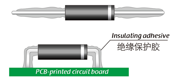
Common treatment methods for surface adhesive insulation:

Characteristics of insulation adhesive material:

1. Silicone material usually presents a transparent and elastic rubber state after curing, which is more effective in shock resistance and can also withstand severe stress changes caused by large high and low temperature changes (-40 ° C~200 ° C).

2. Acrylic materials typically exhibit a transparent and hard coating after curing, with low moisture absorption and fast curing time, as well as excellent wear resistance and insulation.

3. After curing, Urethane material usually presents a transparent and hard coating, which has superior wear resistance and good moisture resistance. Its performance is particularly stable in low temperature environments, but it is less resistant to high temperatures.

4. The coating material based on epoxy is very sturdy and usually opaque, with good moisture and moisture resistance. Its resistance to chemical corrosion and wear is also very good. In addition, epoxy also has good dielectric properties.

Here, suitable insulation adhesive materials can be selected based on the different usage situations of engineers.

HVDIODE - Suly Electronics Co., Ltd.

Expects To Provide You With Perfect Service

Name
Email *
Verification Code *
Click to verify
Leave a message
Name
Email *
Message
Verification Code *
Click to verify
We use Cookie to improve your online experience. By continuing browsing this website, we assume you agree our use of Cookie.