• HV37-Series  Axial Lead Fast Recovery High Voltage Diodes
  • HV37-Series  Axial Lead Fast Recovery High Voltage Diodes
  • HV37-Series  Axial Lead Fast Recovery High Voltage Diodes
  • HV37-Series  Axial Lead Fast Recovery High Voltage Diodes
  • HV37-Series  Axial Lead Fast Recovery High Voltage Diodes
  • HV37-Series  Axial Lead Fast Recovery High Voltage Diodes

HV37-Series Axial Lead Fast Recovery High Voltage Diodes

Params Range:6-20KV;100-500mA;150nS
$0.00
Product type code:
HV37-06 (300mA)
HV37-08 (210mA)
HV37-10 (190mA)
HV37-12 (170mA)
HV37-15 (150mA)
HV37-20 (100mA)
Trr:
100nS
  • HV37-Series  Axial Lead Fast Recovery High Voltage Diodes
  • HV37-Series  Axial Lead Fast Recovery High Voltage Diodes
  • HV37-Series  Axial Lead Fast Recovery High Voltage Diodes
  • Desciption

  • data sheet

  • Package Size

  • Installation Guide

Detailed description of the HV37 series of fast recovery axial high-voltage diodes

一、Product Overview

The HV37 series is a silicon-based fast recovery diode specifically designed for high-frequency and high-voltage rectification. Its core features include a reverse withstand voltage of 6-20kV, an average forward current of 100-500mA, and an ultra-fast reverse recovery time (TRR=100ns).

This device adopts an optimized chip structure and packaging process, and is suitable for scenarios such as high-frequency switching power supplies, pulse power equipment, and medical imaging systems that have strict requirements for voltage response speed and withstand voltage capability.

二、Technical Parameter Table

HV37 series Axial lead rapid Recovery high-voltage diodes (6-20KV; 100-500mA 100nS)

Type Vrrm(KV) If1(mA) If2(mA) Vfm(V) Ifsm(A) TRR(nS) Irrm1/Irrm2(uA) Photo
Condition Ta=25℃ Ir=2uA Ta=40℃(air) Ta=55℃(oil) Max tp=8.3ms 50℃   Ta=25℃/100℃
HV37-06 6 300 500 10.0 15 150 2/10
HV37-08 8 210 400 12.0 15 150 2/10
HV37-10 10 190 370 13.0 15 150 2/10
HV37-12 12 170 340 15.0 15 150 2/10
HV37-15 15 150 300 20.0 15 150 2/10
HV37-20 20 100 220 26.0 15 150 2/10
For parameter customization, please contact our customer service: sales@hvdiode.com


三、Key features and structural design

  1. High-frequency performance optimization
    • Ultra-fast recovery chip:The carrier lifetime is shortened through the diffusion process to achieve TRR=100ns, reduce switching losses and improve high-frequency efficiency.
    • Low parasitic capacitance:Optimize the PN junction design, reduce the junction capacitance (Cj≈5pF), and suppress high-frequency oscillation and noise.
  2. Pressure resistance and reliability
    • Gradient doping technology:The multi-level electric field buffer layer design balances the electric field distribution within the withstand voltage range of 6-20kV, avoiding local breakdown.
    • Epoxy resin encapsulation:High temperature resistance, excellent density, arc resistance, and adaptability to high-voltage and high-frequency environments.

四、Application field

  • Pulse power equipment:High-voltage rectification and freewheeling for laser drivers, Marx generators, and electromagnetic pulse (EMP) simulators.
  • Medical equipment:High-frequency rectification modules for X-ray tube high-voltage power supplies and MRI gradient power supplies
  • Industrial power supply:High-voltage switch circuits for high-frequency dielectric heating power supplies, plasma generators, and electrostatic precipitators.
  • Scientific research instruments:High-voltage pulse modulation systems for particle detectors and radio frequency accelerators.

五、Electrical characteristic curve (typical values)

  1. Forward characteristic:VF vs. IF(Ta=40℃(air)@Nominal value,Ta=55℃(oil) @Nominal value Two conditions)。
  2. Reverse characteristic:IR vs. VR(Leakage current<1μA@6-20kV,<2μA@6-20kV)。
  3. Recovery feature:(TRR≤150ns)。

六、Installation and Usage Guide

  1. PCB layout suggestions
    • The high-voltage wiring spacing should be ≥15mm to avoid the risk of creepage. The area of the high-frequency loop is minimized to reduce radiation interference.
  2. Heat dissipation management
    • It is recommended that the working junction temperature be ≤125℃. In an oil-immersed working environment, a radiator or forced air cooling should be provided (when the ambient temperature is > 50℃).
  3. Protective measures
    • Parallel RC absorption circuit to suppress voltage spikes and oscillations。
    • Avoid mechanical stress impact on the pins. The peak welding temperature should be ≤260℃ (duration < 5 seconds).

七、Quality and Certification

  • Reliability test:通过1000小时老化测试及1000次温度循环(-45℃~+125℃)正向测试。
  • Conform to the standard:IEC 60747-1、ISO9001(2015)及RoHS 2.0、。
  • Quality assurance period:12 months (non-human damage, verification required).

八、Order information

  • Model code:HV37-XX(Complete model identification or neutral identification)。
  • Packaging specification:50 pieces/Anti-static bags, or customized packaging as required。
  • Production cycle:The inventory of standard products is sufficient, and they will be delivered within 1-3 days. Special batches will be delivered within 3-5 weeks. The specific delivery time will be adjusted slightly based on the delivered output。

Remarks:For detailed parameters, please refer to the official data sheet. High frequency application recommendation contact technical support support@hvdiode.com for experimental data verification.

The selection of high-voltage diodes is closely related to their usage environment。

1. Used in insulating oil. (Recommended)
2. Used in insulating gases. (Recommended)
3. Secondary packaging use. (High requirements for heat dissipation and other parameter performance of components)
4. Use in exposed air or add air cooling. (If the size of the high-voltage diode is small, it is easy to discharge, and the heat dissipation performance is average.)

For high-voltage diodes used in exposed air, it is recommended to install them with insulated electrodes at both ends.


Common treatment methods for surface adhesive insulation:

Characteristics of insulation adhesive material:

1. Silicone material usually presents a transparent and elastic rubber state after curing, which is more effective in shock resistance and can also withstand severe stress changes caused by large high and low temperature changes (-40 ° C~200 ° C).

2. Acrylic materials typically exhibit a transparent and hard coating after curing, with low moisture absorption and fast curing time, as well as excellent wear resistance and insulation.

3. After curing, Urethane material usually presents a transparent and hard coating, which has superior wear resistance and good moisture resistance. Its performance is particularly stable in low temperature environments, but it is less resistant to high temperatures.

4. The coating material based on epoxy is very sturdy and usually opaque, with good moisture and moisture resistance. Its resistance to chemical corrosion and wear is also very good. In addition, epoxy also has good dielectric properties.

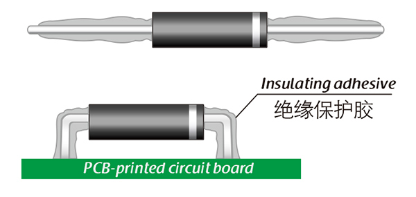
Here, suitable insulation adhesive materials can be selected based on the different usage situations of engineers.

HVDIODE - Suly Electronics Co., Ltd.

Expects To Provide You With Perfect Service

Name
Email*
Verification Code*
Verification Code
Leave a message
Name
Email*
Message
Verification Code*
Verification Code
We use Cookie to improve your online experience. By continuing browsing this website, we assume you agree our use of Cookie.