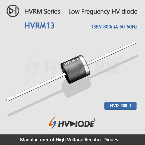
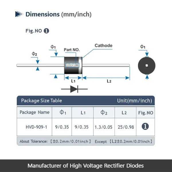
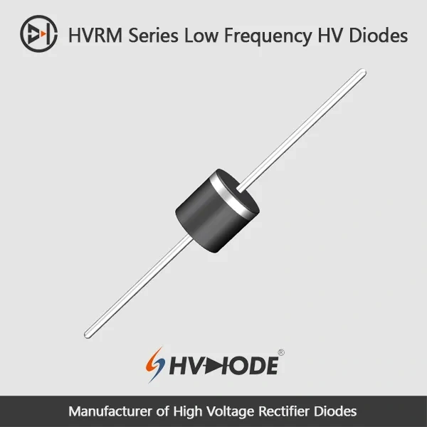
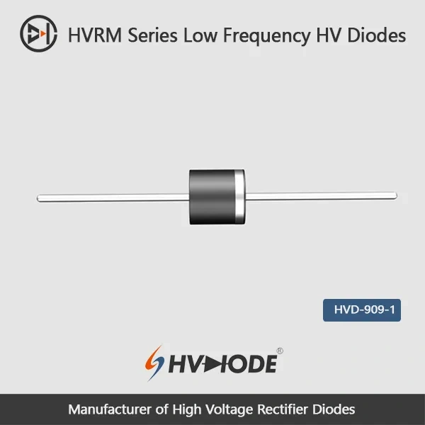
| HVRM13 Low frequency high voltage diode Data Sheet | ||||
| Parameter | Symbol | Unit | Test Conditions | Value |
| Repetitive Peak Backward Voltage | Vrrm | KV | Ta=25℃ Ir=2.0μA | 13 |
| Peak Working Backward Voltage | Vrwm | KV | Ta=25℃ Ir=2.0μA | 13 |
| Average Forward Current | If(AV) | A | 50Hz Half-sine Wave , Resistance load @Tbreak=50℃ | 0.8 |
| Backward Recovery Time | Trr | nS | -- | |
| Surge Forward Current | Ifsm | A | 0.01S @ Half-Sine wave 50Hz | 80 |
| Operating Ambient Temperature | Ta | ℃ | -55~+175 | |
| Storage Temperature | Tstg | ℃ | -55~+150 | |
| Forward Peak Voltage | Vfm | V | ≥15.6 | |
| Backward Peak Current | Irrm1 | μA | @ Ta=25℃ VRM=VRRM | 2.0 |
| Irrm2 | μA | @ Ta=100℃ VRM=VRRM | 20.0 | |
| Absolute Maximum Ratings & Electrical Characteristics | ||||
Where the diode is mounted matters as much as the rating. Immersion in insulating oil is the recommended arrangement, and insulating gas is the next most suitable option, because both media suppress discharge around the high-voltage terminations and carry heat away from the body. A potted or secondarily enclosed assembly is workable, but the potting compound and the neighbouring components then have to cope with the heat the diode produces, so the thermal design deserves closer attention there. Open-air mounting is possible, although a small high-voltage diode in free air is more prone to discharge at the electrodes and dissipates heat only averagely; where it cannot be avoided, fit insulated electrodes at both ends and consider forced-air cooling. In every case, keep the high-voltage surfaces clean, dry and free of solder flux.
Selection support starts before you order. Our technical team reviews your working voltage, forward current, surge and thermal conditions against the published datasheets, then recommends the closest high-voltage diode and confirms the matching part number. We also guide you through installation and insulation considerations, and help troubleshoot issues during qualification or after delivery. Suly Electronics manufactures these diodes directly, supplies them in bulk, and keeps answering technical questions for the parts you already use.
It is built for 50-60 Hz rectification in bridge rectifier stacks, high-voltage rectifier assemblies and diode PCB positions. Like most high voltage diodes in the power-frequency class, it is chosen for its blocking voltage first and its current rating second, so it fits circuits where the voltage is high and the load current stays modest.
No. This is a power-frequency part built for 50-60 Hz operation, and its reverse recovery time is not specified on the data sheet, which is normal for a low-frequency rectifier. A switching supply or inverter needs a fast or ultra-fast recovery diode instead; tell us the switching frequency and the blocking voltage and we will match one from our range.
Leave margin between your highest reverse voltage and the blocking rating, and allow for transients on the supply. If your working voltage sits close to the top of this part's range, step up to the next voltage level in the HVRM series, where the same current class continues, so the change is usually simple for the circuit designer. Tell us the working voltage and the transient you expect and we will confirm the level that gives you the margin you want.
Reverse leakage rises with junction temperature. At the 25 °C test condition the data sheet limit is 2.0 µA, and at 100 °C it is 20.0 µA, so a warm board can show leakage well above a room-temperature measurement and high-temperature designs should be checked against the 100 °C figure.
Yes. The average forward current is quoted for a 50 Hz half-sine wave with a resistive load at a 50 °C break point, so a diode inside a hot enclosure or a potted module will not carry the same current as one sitting in oil. Improve the thermal path, whether that is oil or gas immersion, a heat sink or forced air, or reduce the load current, and send us your cooling arrangement if you want us to confirm a safe operating point.
Both are available. The data sheet carries the absolute maximum ratings and electrical characteristics, and the installation guide covers mounting and insulation practice. As high voltage diode manufacturers we send the revision that matches your order, so your engineering team is reviewing the same numbers the part was built to.
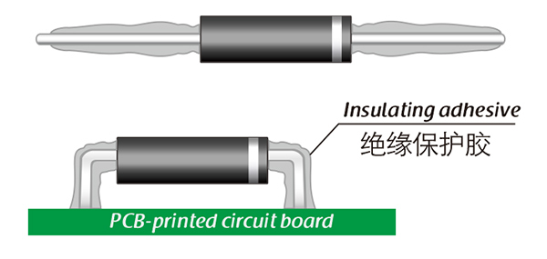
Here, suitable insulation adhesive materials can be selected based on the different usage situations of engineers.