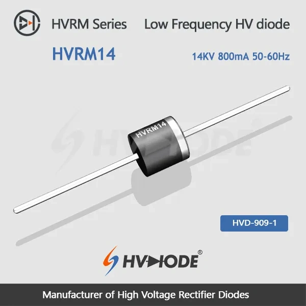
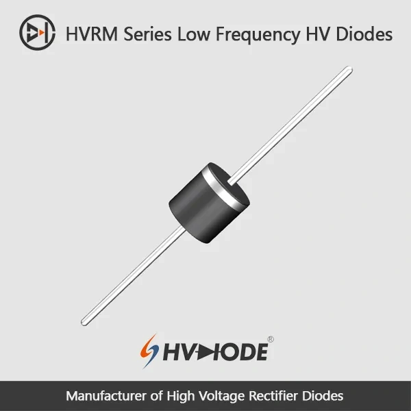
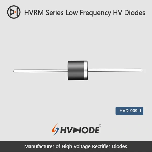
• HVRM14- Low frequency high voltage diode 14KV,0.8A,50-60Hz
  • HVRM14- Low frequency high voltage diode 14KV,0.8A,50-60Hz
  • HVRM14- Low frequency high voltage diode 14KV,0.8A,50-60Hz
  • HVRM14- Low frequency high voltage diode 14KV,0.8A,50-60Hz
  • HVRM14- Low frequency high voltage diode 14KV,0.8A,50-60Hz
  • HVRM14- Low frequency high voltage diode 14KV,0.8A,50-60Hz
  • HVRM14- Low frequency high voltage diode 14KV,0.8A,50-60Hz
  • HVRM14- Low frequency high voltage diode 14KV,0.8A,50-60Hz

HVRM14- Low frequency high voltage diode 14KV,0.8A,50-60Hz

No.HVRM14
Products Main features:
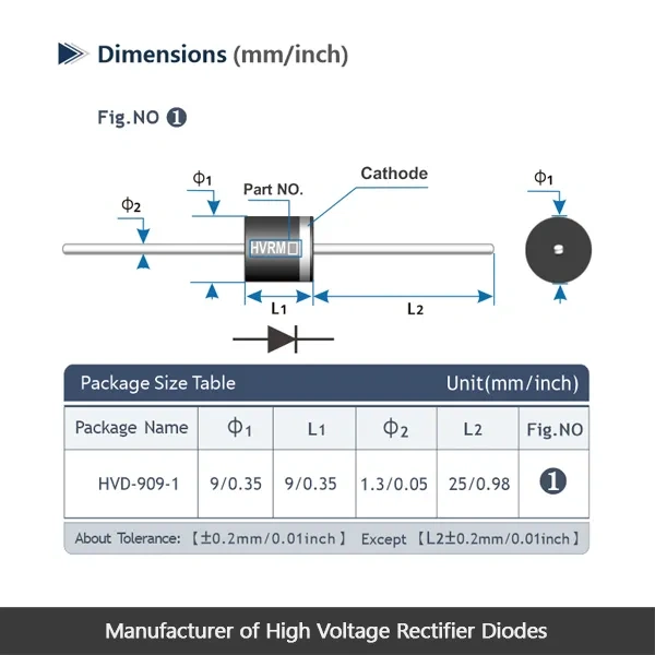
1、Axial leaded connection.
2、High thermal conductivity epoxy compound molding.
3、Excellent surge current resistance
4、Special high temperature resistant chip
  • HVRM14- Low frequency high voltage diode 14KV,0.8A,50-60Hz
  • HVRM14- Low frequency high voltage diode 14KV,0.8A,50-60Hz
  • HVRM14- Low frequency high voltage diode 14KV,0.8A,50-60Hz
  • HVRM14- Low frequency high voltage diode 14KV,0.8A,50-60Hz
  • Desciption

  • data sheet

  • Installation Guide

 HVRM14  Low frequency high voltage diode Data Sheet 
 Parameter Symbol Unit Test Conditions Value
 Repetitive Peak Backward Voltage Vrrm KV Ta=25℃  Ir=2.0μA 14
 Peak Working Backward Voltage Vrwm KV Ta=25℃  Ir=2.0μA 14
 Average Forward Current If(AV) A 50Hz Half-sine Wave , Resistance load @Tbreak=50℃ 0.8
 Backward Recovery Time Trr nS   --
 Surge Forward Current Ifsm A 0.01S @ Half-Sine wave  50Hz 80
 Operating Ambient Temperature Ta ℃   -55~+175
 Storage Temperature Tstg ℃   -55~+150
 Forward Peak Voltage Vfm V   ≥17.0
 Backward Peak  Current Irrm1 μA @ Ta=25℃ VRM=VRRM 2.0
Irrm2 μA @ Ta=100℃ VRM=VRRM 20.0
 Absolute Maximum Ratings & Electrical Characteristics


Operating Environment

  • Insulating oil (recommended). The classic way to run high voltage diodes at this level. The oil fills the space around the body and leads, keeps surface discharge down and carries heat away from the chip, so choose it whenever the assembly can be sealed.
  • Insulating gas (recommended). A good alternative where oil is impractical, with the same benefit of a controlled field around the diode. The enclosure has to hold the gas and keep moisture out for the advantage to hold.
  • Secondary packaging. Potting or encapsulating the diode protects it mechanically and electrically, but it raises the demand on heat dissipation and on the other parameters, so the compound and the layout around the diode both matter.
  • Open air or air-cooled mounting. A small body running at 14 kV in open air can discharge across its own surface, and heat dissipation is only average. If the diode has to sit in air, mount it with insulated electrodes at both ends, give it clearance and use air movement to help.

Circuit Applications

  • Mains-frequency rectifier stages. The natural home for this part: a 50-60 Hz transformer feeding a rectifier in a high-voltage DC supply, where the diode blocks the peak transformer voltage on every cycle.
  • Rectifier stacks and bridge assemblies. High-voltage legs are usually built from a series string of diodes; a 14 kV device carries more of that voltage on its own, so the string is shorter and easier to lay out.
  • Diode boards and rebuilds. Through-hole axial mounting suits boards that come back for repair, where the failed device is swapped and the board returned to service.
  • Laboratory and prototype supplies. One-off high-voltage circuits where a published data sheet and a known blocking rating matter more than volume.
  • Field service and spares. Keeping one rating on the shelf covers the rectifier boards that fail most often in service.

Model Reference & Replacement

Replacement usually starts with the number marked on the old diode. The HVRM range steps from 5 kV to 15 kV, and this model sits in the 0.8 A current tier alongside the 13 kV and 15 kV versions, so a design can move one step up or down in voltage without leaving the same current class. Order by the marked part number, then confirm two things before you commit: the peak reverse voltage your circuit can actually produce, including transients, and the lead form and footprint on the board, because the right rating in the wrong footprint still will not drop in. Every rating comes off our own line, so changing voltage does not mean changing high voltage diode manufacturers or re-qualifying a new process.

Technical Support & Model Matching

Selection support starts before you order. Our technical team reviews your working voltage, forward current, surge and thermal conditions against the published datasheets, then recommends the closest high-voltage diode and confirms the matching part number. We also guide you through installation and insulation considerations, and help troubleshoot issues during qualification or after delivery. Suly Electronics manufactures these diodes directly, supplies them in bulk, and keeps answering technical questions for the parts you already use.

FAQ

Q1. Can this diode be used above 50-60 Hz?

No. It is built for low-frequency rectification, and no reverse recovery time is published for it. If your circuit switches in the kilohertz range, choose one of our fast recovery diodes instead; for mains-frequency rectifier stages this part is the correct type.

Q2. What is the difference between Vrrm and Vrwm?

Vrrm is the repetitive peak reverse voltage the diode blocks in normal, repeated operation. Vrwm is the peak working reverse voltage under the same condition. Both are 14 kV on this model, so the figure you plan around for continuous rectification is the same one quoted for working voltage.

Q3. How does reverse leakage change as the diode warms up?

At rated reverse voltage, leakage is 2.0 µA at 25 °C and rises to 20.0 µA at 100 °C. That rise is normal for a diode in this class, but it matters in high-impedance circuits, so check the leakage budget wherever a small reverse current cannot be tolerated.

Q4. What does Vfm ≥17.0 V mean for my circuit?

It is the peak forward voltage across the diode under its rated forward condition. A 14 kV device has to hold off far more voltage than a low-voltage rectifier, and that capability shows up as a higher forward drop, which becomes heat while current flows. Check the figure against your loss budget before finalizing the design.

Q5. How should I store diodes that are not going into production yet?

Keep them in the original packaging in a dry store and within the storage temperature range shown on the data sheet. Leave the pack sealed until the parts are needed, and handle the leads carefully so they stay straight for the assembly line.

Q6. Is there anything special about forming and soldering the leads?

Treat them like any axial through-hole semiconductor. Support the lead where it leaves the body, make the bend away from the seal, and keep soldering heat brief. The cured epoxy body itself is robust; the lead-to-body seal is the part worth protecting.
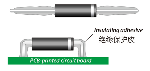
The selection of high-voltage diodes is closely related to their usage environment。

1. Used in insulating oil. (Recommended)
2. Used in insulating gases. (Recommended)
3. Secondary packaging use. (High requirements for heat dissipation and other parameter performance of components)
4. Use in exposed air or add air cooling. (If the size of the high-voltage diode is small, it is easy to discharge, and the heat dissipation performance is average.)

For high-voltage diodes used in exposed air, it is recommended to install them with insulated electrodes at both ends.


Common treatment methods for surface adhesive insulation:

Characteristics of insulation adhesive material:

1. Silicone material usually presents a transparent and elastic rubber state after curing, which is more effective in shock resistance and can also withstand severe stress changes caused by large high and low temperature changes (-40 ° C~200 ° C).

2. Acrylic materials typically exhibit a transparent and hard coating after curing, with low moisture absorption and fast curing time, as well as excellent wear resistance and insulation.

3. After curing, Urethane material usually presents a transparent and hard coating, which has superior wear resistance and good moisture resistance. Its performance is particularly stable in low temperature environments, but it is less resistant to high temperatures.

4. The coating material based on epoxy is very sturdy and usually opaque, with good moisture and moisture resistance. Its resistance to chemical corrosion and wear is also very good. In addition, epoxy also has good dielectric properties.

Here, suitable insulation adhesive materials can be selected based on the different usage situations of engineers.

HVDIODE - Suly Electronics Co., Ltd.

Expects To Provide You With Perfect Service

Name
Email *
Verification Code *
Verification Code
Leave a message
Name
Email *
Message
Verification Code *
Verification Code
We use Cookie to improve your online experience. By continuing browsing this website, we assume you agree our use of Cookie.