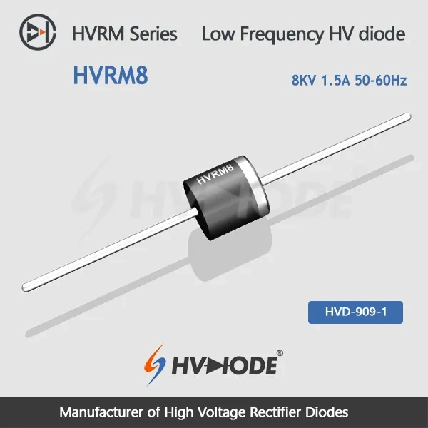
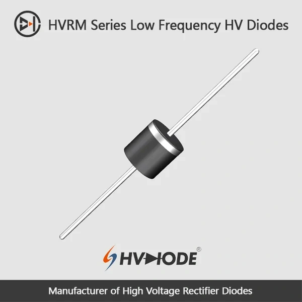
| HVRM8 Low frequency high voltage diode Data Sheet | ||||
| Parameter | Symbol | Unit | Test Conditions | Value |
| Repetitive Peak Backward Voltage | Vrrm | KV | Ta=25℃ Ir=2.0μA | 8 |
| Peak Working Backward Voltage | Vrwm | KV | Ta=25℃ Ir=2.0μA | 8 |
| Average Forward Current | If(AV) | A | 50Hz Half-sine Wave , Resistance load @Tbreak=50℃ | 1.5 |
| Backward Recovery Time | Trr | nS | -- | |
| Surge Forward Current | Ifsm | A | 0.01S @ Half-Sine wave 50Hz | 150 |
| Operating Ambient Temperature | Ta | ℃ | -55~+175 | |
| Storage Temperature | Tstg | ℃ | -55~+150 | |
| Forward Peak Voltage | Vfm | V | ≥9.6 | |
| Backward Peak Current | Irrm1 | μA | @ Ta=25℃ VRM=VRRM | 2.0 |
| Irrm2 | μA | @ Ta=100℃ VRM=VRRM | 20.0 | |
| Absolute Maximum Ratings & Electrical Characteristics | ||||
Where the diode sits affects how well it holds its rating. Immersion in insulating oil is the arrangement we recommend first: the oil carries heat away from the body and suppresses the surface discharges that build around any high-voltage junction. Sealed insulating gas gives a similar result inside gas-filled enclosures. When the diode is potted or given a secondary encapsulation, the surrounding compound becomes its heat path, so dissipation and the compound's behaviour over temperature deserve attention at the design stage. In open air, or with added air cooling, a small high-voltage diode is more likely to discharge across its own surface and its heat path is only average — mount it with insulated electrodes at both ends so the field is spread and the leads are not the weakest point.
Yes. It is a power-frequency rectifier diode and the 50-60 Hz marking covers both line frequencies used for low-frequency rectification. The ratings in the data sheet describe this operating band, so a 60 Hz supply needs no change to the part number or to the surrounding circuit.
No. This is a low-frequency rectifier built for 50-60 Hz operation, and its backward recovery time is left unspecified because switching speed is not part of its job. If your circuit switches at kilohertz or above, choose from our ultra-fast recovery high voltage diodes instead — they are made for that duty.
Choose the lowest blocking rating that still covers your worst-case reverse voltage with margin. The 7 KV, 8 KV and 9 KV parts in this family step the voltage by 1 KV while staying in the same current class, so moving one step up or down normally means no other change to the rectifier design. Confirm the peak voltage in your circuit against the data sheet before you commit.
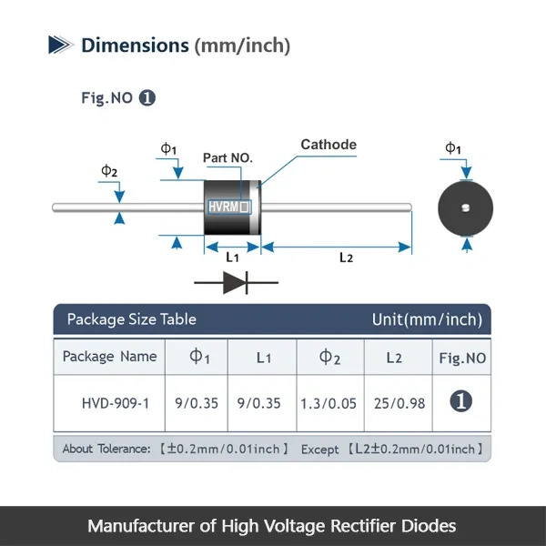
Compare three things against the part you are replacing: repetitive peak reverse voltage, average forward current and lead form. If the three line up, this high voltage diode is a like-for-like fit. If the old part carries more current, step up within the range rather than running this one hot.
A full data sheet and a separate installation guide. The data sheet lists the absolute maximum ratings and electrical characteristics — the surge and leakage figures a design file needs — and the installation guide covers mounting. Both come from us directly: we are high voltage diode manufacturers, so the figures are our own and technical questions return to the same team.
Keep them in their original packaging in a dry area and within the storage temperature range given in the data sheet. The leads are the most easily damaged part of the body, so leave them straight until you are ready to fit the diode, and avoid storing loose parts where the leads can be knocked out of line.
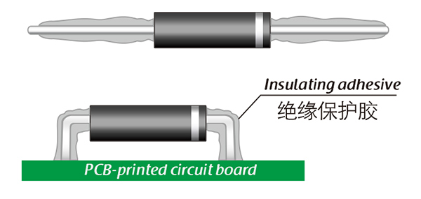
Here, suitable insulation adhesive materials can be selected based on the different usage situations of engineers.