• HVP10-3 Trapeziform High Voltage Rectifier Blocks 10KV 3A  50-60Hz
  • HVP10-3 Trapeziform High Voltage Rectifier Blocks 10KV 3A  50-60Hz
  • HVP10-3 Trapeziform High Voltage Rectifier Blocks 10KV 3A  50-60Hz
  • HVP10-3 Trapeziform High Voltage Rectifier Blocks 10KV 3A  50-60Hz
  • HVP10-3 Trapeziform High Voltage Rectifier Blocks 10KV 3A  50-60Hz
  • HVP10-3 Trapeziform High Voltage Rectifier Blocks 10KV 3A  50-60Hz
  • HVP10-3 Trapeziform High Voltage Rectifier Blocks 10KV 3A  50-60Hz
  • HVP10-3 Trapeziform High Voltage Rectifier Blocks 10KV 3A  50-60Hz
  • HVP10-3 Trapeziform High Voltage Rectifier Blocks 10KV 3A  50-60Hz
  • HVP10-3 Trapeziform High Voltage Rectifier Blocks 10KV 3A  50-60Hz

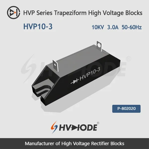
HVP10-3 Trapeziform High Voltage Rectifier Blocks 10KV 3A 50-60Hz

No.HVP10-3
Product main features:
1. Quick connect tab or Turret type terminals.
2. Special Plastic case body, Epoxy filled.
3. Excellent surge current resistance.
4. Layered chip stacked  structure.
5. high temperature resistant chip.
  • HVP10-3 Trapeziform High Voltage Rectifier Blocks 10KV 3A  50-60Hz
  • HVP10-3 Trapeziform High Voltage Rectifier Blocks 10KV 3A  50-60Hz
  • HVP10-3 Trapeziform High Voltage Rectifier Blocks 10KV 3A  50-60Hz
  • HVP10-3 Trapeziform High Voltage Rectifier Blocks 10KV 3A  50-60Hz
  • HVP10-3 Trapeziform High Voltage Rectifier Blocks 10KV 3A  50-60Hz
  • Desciption

  • Discharge problem

 HVP10-3 Trapeziform High Voltage Rectifier Blocks  Data Sheet 
 Parameter Symbol Unit Test Conditions Value
 Repetitive Peak Backward Voltage Vrrm KV Ta=25℃  Ir=2.0μA 10.0
 Peak Working Backward Voltage Vrwm KV Ta=25℃  Ir=2.0μA 10.0
 Average Forward Current If(AV) A 50Hz Half-sine Wave , Resistance load @Tbreak=50℃ 3.0
 Backward Recovery Time Trr nS   --
 Surge Forward Current Ifsm A 0.01S @ Half-Sine wave  50Hz 120
 Operating Ambient Temperature Ta   -55~+175
 Storage Temperature Tstg   -55~+150
 Forward Peak Voltage Vfm V   ≥12.0
 Backward Peak  Current Irrm1 μA @ Ta=25℃ VRM=VRRM 2.0
Irrm2 μA @ Ta=100℃ VRM=VRRM 20.0
 Absolute Maximum Ratings & Electrical Characteristics
The selection of high-voltage diodes is closely related to their usage environment。

1. Used in insulating oil. (Recommended)
2. Used in insulating gases. (Recommended)
3. Secondary packaging use. (High requirements for heat dissipation and other parameter performance of components)
4. Use in exposed air or add air cooling. (If the size of the high-voltage diode is small, it is easy to discharge, and the heat dissipation performance is average.)

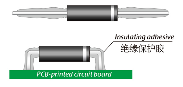
For high-voltage diodes used in exposed air, it is recommended to install them with insulated electrodes at both ends.


Common treatment methods for surface adhesive insulation:

Characteristics of insulation adhesive material:

1. Silicone material usually presents a transparent and elastic rubber state after curing, which is more effective in shock resistance and can also withstand severe stress changes caused by large high and low temperature changes (-40 ° C~200 ° C).

2. Acrylic materials typically exhibit a transparent and hard coating after curing, with low moisture absorption and fast curing time, as well as excellent wear resistance and insulation.

3. After curing, Urethane material usually presents a transparent and hard coating, which has superior wear resistance and good moisture resistance. Its performance is particularly stable in low temperature environments, but it is less resistant to high temperatures.

4. The coating material based on epoxy is very sturdy and usually opaque, with good moisture and moisture resistance. Its resistance to chemical corrosion and wear is also very good. In addition, epoxy also has good dielectric properties.

Here, suitable insulation adhesive materials can be selected based on the different usage situations of engineers.

HVDIODE - Suly Electronics Co., Ltd.

Expects To Provide You With Perfect Service

FirstName*
LastName*
Email*
We use Cookie to improve your online experience. By continuing browsing this website, we assume you agree our use of Cookie.